

LTA201P Datasheet – SMPS control IC – SOP 14 – Philips
SMPS control IC, PWM Controller IC
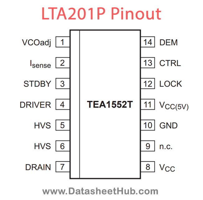
LTA201P overview
The LTA201P is an SMPS control IC, PWM Controller IC made by Philips Electronics - NXP, supplied in an SOP 14 Pin package. The absolute maximum ratings table on this page lists the 20 limits from the manufacturer's datasheet that must not be exceeded. This page brings together the LTA201P pinout and maximum ratings, with the full datasheet PDF to preview below or download.
The GreenChipII is the second generation of green Switched Mode Power Supply (SMPS) control ICs operating directly from the rectified universal mains. A high level of integration leads to a cost effective power supply with a very low number of external components.
The special built-in green functions allow the efficiency to be optimum at all power levels. This holds for quasi-resonant operation at high power levels, as well as fixed frequency operation with valley switching at medium power levels. At low power (standby) levels, the system operates at reduced frequency and with valley detection.
The proprietary high voltage BCD800 process makes direct start-up possible from the rectified mains voltage in an effective and green way. A second low voltage BICMOS IC is used for accurate, high speed protection functions and control.
Highly efficient, reliable supplies can easily be designed using the GreenChipII control IC.
Datasheet
LTA201P features
- Distinctive features
- Universal mains supply operation (70 V AC to 276 V AC)
- High level of integration, giving a very low external component count.
- Green features
- Valley or zero voltage switching for minimum switching losses
- Efficient quasi-resonant operation at high power levels
- Frequency reduction at low power standby for improved system efficiency (<3 W)
- Cycle skipping mode at very low loads. Pi < 300 mW at no-load operation for a typical adapter application
- On-chip start-up current source
- Standby indication pin to indicate low output power consumption.
- Protection features
- Safe restart mode for system fault conditions
- Continuous mode protection by means of demagnetization detection (zero switch-on current)
- Accurate and adjustable overvoltage protection (latched)
- Short winding protection
- Undervoltage protection (foldback during overload)
- Overtemperature protection (latched)
LTA201P pinout
| Pin | Name | Description |
|---|---|---|
| 1 | VCOadj | VCO adjustment input |
| 2 | Isense | programmable current sense input |
| 3 | STDBY | standby indication or control output |
| 4 | DRIVER | gate driver output |
| 5 | HVS | high voltage safety spacer, not connected |
| 6 | HVS | high voltage safety spacer, not connected |
| 7 | DRAIN | drain of external MOS switch, input for start-up current and valley sensing |
| 8 | VCC | supply voltage |
| 9 | NC | not connected |
| 10 | GND | ground |
| 11 | VCC (5v) | 5 V output |
| 12 | LOCK | lock input |
| 13 | CTRL | control input |
| 14 | DEM | input from auxiliary winding for demagnetization timing, OVP and OPP |
Absolute maximum ratings
| Parameter | Symbol | Value | Unit | Conditions |
|---|---|---|---|---|
| voltage on pin VCOadj | VVCOadj | Min -0.4 / Max +5 | V | continuous |
| voltage on pin Isense | Vsense | Min -0.4 | V | current limited |
| voltage on pin DRAIN | VDRAIN | Min -0.4 / Max +650 | V | |
| supply voltage | VCC | Min -0.4 / Max +20 | V | continuous |
| voltage on pin LOCK | VLOCK | Min -0.4 / Max +7 | V | continuous |
| voltage on pin CTRL | VCTRL | Min -0.4 / Max +5 | V | |
| voltage on pin DEM | VDEM | Min -0.4 | V | current limited |
| current on pin Isense | Isense | Min -1 / Max +10 | mA | |
| current on pin STDBY | ISTDBY | Min -1 | mA | |
| current on pin DRIVER | IDRIVER | Min -0.8 / Max +2 | A | d < 10 % |
| current on pin DRAIN | IDRAIN | Max +5 | mA | |
| current on pin VCC(5V) | ICC(5V) | Min -1 / Max 0 | mA | |
| current on pin CTRL | ICTRL | Max +5 | mA | |
| current on pin DEM | IDEM | Min -250 / Max +250 | mA | |
| total power dissipation | Ptot | Max 0.75 | W | Tamb < 70 °C |
| storage temperature | Tstg | Min -55 / Max +150 | °C | |
| junction temperature | Tj | Min -20 / Max +145 | °C | |
| pins 1 to 6 and pins 9 to 14 HBM class 1 | Min V | 2000 | ||
| pin 7 HBM class 1 | Min V | 1500 | ||
| on any other pin MM | Min V | 400 |
LTA201P applications
- Typical application areas are adapters and chargers (e.g. for laptops, camcorders and printers) and all applications that demand an efficient and cost-effective solution up to 250 W.
- Phototransistor Applications
- Optical Sensing Systems
- Light Detection Circuits
- Proximity Sensing Devices
Comments 0
Leave a comment