

SAA7201H Datasheet – Integrated MPEG2 AVG Decoder
3.3 V, integrated MPEG2 AVG Decoder
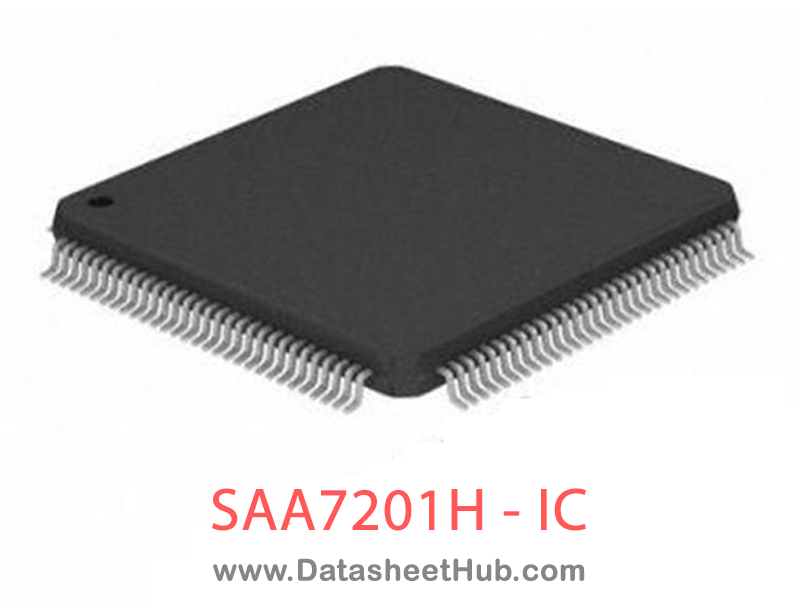
SAA7201H overview
The SAA7201H is a 3.3 V, integrated MPEG2 AVG Decoder made by Philips Electronics - NXP, supplied in a QFP160 Type package. The absolute maximum ratings table on this page lists the 5 limits from the manufacturer's datasheet that must not be exceeded. This page brings together the SAA7201H pinout and maximum ratings, with the full datasheet PDF to preview below or download.
The SAA7201 is an MPEG2 decoder which combines audio decoding and video decoding. Additionally to these basic MPEG functions it also provides means for enhanced graphics and/or on-screen display.Due to an optimized architecture for audio and video decoding, maximum capacity in the external memory and processing power from the external CPU is available for the support for graphics
Datasheet
SAA7201H features
- General
- Uses single external Synchronous DRAM (SDRAM) organized as 1M ´ 16 interfacing at 81 MHz; compatible with the SDRAM ‘lite’ or ‘PC’
- Fast external CPU interface; 16-bit data + 8-bit address
- Dedicated input for audio and video data in PES or ES format; data input rate: £9 Mbytes/s in byte mode;
- £20 Mbit/s in bit serial mode; audio and/or video data can also serve as input via CPU interface
- Single 27 MHz external clock for time base reference and internal processing; all required decoding and presentation clocks are generated internally
- Internal system time base at 90 kHz can be synchronized via CPU port
- Flexible memory allocation under control of the external CPU enables optimized partitioning of memory for different tasks
- Boundary scan (JTAG) plus external SDRAM self test implemented
- Supply voltage 3.3 V
- Package 160 QFP.
- CPU relation
- 16-bit data, 8-bit address, or 16-bit multiplexed bus; Motorola and Intel mode supported
- Support for fast DMA transfer to either internal registers or external SDRAM
- Maximum sustained rate to the external SDRAM is 9 Mbytes/s.
- MPEG2 system
- Parsing of MPEG2 PES and MPEG1 packet streams
- Double System Time Clock (STC) counters for discontinuity handling
- Time stamps or CPU controlled audio/video synchronization
- Support for seamless time base change (edition)
- Processing of errors flagged by channel decoding or demux section
- Support for retrieval of PES header and PES private data.
- MPEG2 audio
- Decoding of 2 channel, layer I and II MPEG audio; support for mono, stereo, intensity stereo and dual channel mode
- Constant and variable bit rates up to 448 kbit/s
- Audio sampling frequencies: 48, 44.1, 32, 24, 22.05 and 16 kHz
- CRC error detection
- Selectable output channel in dual channel mode
- Independent volume control for both channels and programmable inter-channel crosstalk control through a baseband audio processing unit
- Storage ancillary data up to 54 bytes
- Dynamic range control at output
- Muting possibility via external controller; automatic muting in case of errors
- Generation of ‘beeps’ with programmable tone height, duration and amplitude
- Serial two channel digital audio output with 16, 18, 20 or 22 bits per sample, compatible with either I2S or Japanese formats
- Serial SPDIF audio output
- Clock output 256 or 384 ´ fs for external D/A converter
- Audio input buffer in external SDRAM with programmable size (default is 64 kbit)
- Programmable processing delay compensation
- Software controlled stop, pause, restricted skip, and restart functions.
- MPEG2 video Decoding of MPEG2 video up to main level, main profile Nominal video input buffer size equals 2.6 Mbit for Video Main Profile and Main Level (MP@ML) Output picture format: CCIR-601 4 : 2 : 2 interlaced pictures; picture format 720 ´ 576 at 50 Hz or 720 ´ 480 at 60 Hz 3 : 2 pull-down supported with 24 and 30 Hz sequences Support of constant and variable bit rates up to 15 Mbit/s Output
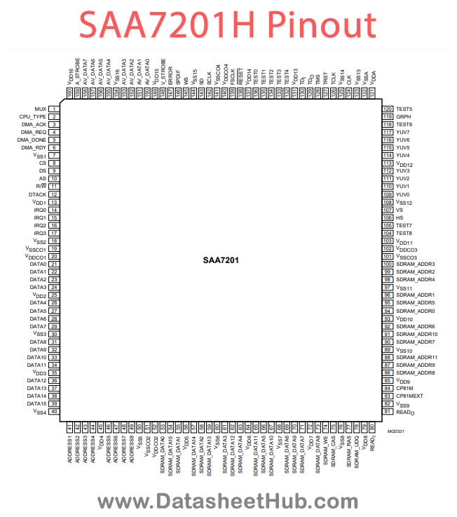
SAA7201H pinout
| Pin | Name | Description |
|---|---|---|
| 1 | MUX | multiplexed/non-multiplexed (active LOW) bus input |
| 2 | CPU_TYPE | Intel/Motorola (active LOW) selection input |
| 3 | DMA_ACK | DMA acknowledge input |
| 4 | DMA_REQ | DMA request input and output |
| 5 | DMA_DONE | DMA end input |
| 6 | DMA_RDY | DMA ready output |
| 7 | VSS1 | ground for pad ring |
| 8 | CS | chip select input |
| 9 | DS | data strobe input |
| 10 | AS | address strobe input |
| 11 | R/W | read/write (active LOW) input |
| 12 | DTACK | data acknowledge output |
| 13 | VDD1 | supply for pad ring |
| 14 | IRQ0 | individually maskable interrupts |
| 15 | IRQ1 | individually maskable interrupts |
| 16 | IRQ2 | individually maskable interrupts |
| 17 | IRQ3 | individually maskable interrupts |
| 18 | VSS2 | ground for pad ring |
| 19 | VSSCO1 | ground for core logic |
| 20 | VDDCO1 | supply for core logic |
| 21 | DATA0 | CPU data interface |
| 22 | DATA1 | CPU data interface |
| 23 | DATA2 | CPU data interface |
| 24 | DATA3 | CPU data interface |
Show all 40 pins
| Pin | Name | Description |
|---|---|---|
| 25 | VDD2 | supply for pad ring |
| 26 | DATA4 | CPU data interface |
| 27 | DATA5 | CPU data interface |
| 28 | DATA6 | CPU data interface |
| 29 | DATA7 | CPU data interface |
| 30 | VSS3 | ground for pad ring |
| 31 | DATA8 | CPU data interface |
| 32 | DATA9 | CPU data interface |
| 33 | DATA10 | CPU data interface |
| 34 | DATA11 | CPU data interface |
| 35 | VDD3 | supply for pad ring |
| 36 | DATA12 | CPU data interface |
| 37 | DATA13 | CPU data interface |
| 38 | DATA14 | CPU data interface |
| 39 | DATA15 | CPU data interface |
| 40 | VSS4 | ground for pad ring |
Absolute maximum ratings
| Parameter | Symbol | Value | Unit | Conditions |
|---|---|---|---|---|
| supply voltage (on all supply pins) | VDD | Min. 3.0 / Max. 3.6 | V | |
| maximum voltage on all pins | Vmax | Min. 0 / Max. 5.5 | V | |
| total power dissipation | Ptot | Max. tbf | W | Tamb = 25 °C |
| storage temperature | Tstg | Min. -55 / Max. +150 | °C | |
| operating ambient temperature | Tamb | Min. 0 / Max. +70 | °C |
SAA7201H applications
- Digital Video Recorders (DVRs)
- Set-Top Boxes
- Media Players
- Video Streaming Devices
Comments 0
Leave a comment