

ADG508F Datasheet – 8-Ch Fault Protected Analog Multiplexer
8-Channel Fault Protected Analog Multiplexer
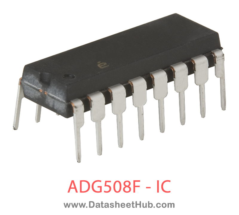
ADG508F overview
The ADG508F is an 8-Channel Fault Protected Analog Multiplexer made by Analog Devices, supplied in a 16-Lead PDIP Package package. The absolute maximum ratings table on this page lists the 13 limits from the manufacturer's datasheet that must not be exceeded. This page brings together the ADG508F pinout and maximum ratings, with the full datasheet PDF to preview below or download.
The ADG508F and ADG509F are CMOS analog multiplexers, with the ADG508F comprising eight single channels and the ADG509F comprising four differential channels. These multiplexers provide fault protection. Using a series n-channel, p-channel, n-channel MOSFET structure, both device and signal source protection is provided in the event of an overvoltage or
power loss. The multiplexer can withstand continuous overvolt- age inputs from −40 V to +55 V. During fault conditions with power supplies off, the multiplexer input (or output) appears as an open circuit and only a few nanoamperes of leakage current will flow. This protects not only the multiplexer and the circuitry driven by the multiplexer, but also protects the sensors or signal sources that drive the multiplexer.
The ADG508F switches one of eight inputs to a common output as determined by the 3-bit binary address lines A0, A1, and A2. The ADG509F switches one of four differential inputs to a common differential output as determined by the 2-bit binary address lines A0 and A1. An EN input on each device is used to enable or disable the device. When disabled, all channels are switched off
Datasheet
ADG508F features
- All switches off with power supply off
- Analog output of on channel clamped within power supplies if an overvoltage occurs
- Latch-up proof construction
- Low on resistance (270 Ω typical)
- Fast switching times tON: 230 ns maximum tOFF: 130 ns maximum
- Low power dissipation (3.3 mW maximum)
- Fault and overvoltage protection (−40 V to +55 V) Break-before-make construction
- TTL and CMOS compatible inputs
ADG508F pinout
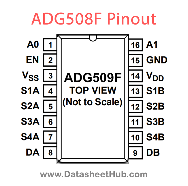
| Pin | Name | Description |
|---|---|---|
| 1 | A0 | Logic Control Input. |
| 2 | EN | Active High Digital Input. When low, the device is disabled and all switches are off. When high, Ax logic inputs determine on switches. |
| 3 | VSS | Most Negative Power Supply Potential. In single-supply applications, this pin can be connected to ground. |
| 4 | S1 | Source Terminal 1. This pin can be an input or an output. |
| 5 | S2 | Source Terminal 2. This pin can be an input or an output. |
| 6 | S3 | Source Terminal 3. This pin can be an input or an output. |
| 7 | S4 | Source Terminal 4. This pin can be an input or an output. |
| 8 | D | Drain Terminal. This pin can be an input or an output. |
| 9 | S8 | Source Terminal 8. This pin can be an input or an output. |
| 10 | S7 | Source Terminal 7. This pin can be an input or an output. |
| 11 | S6 | Source Terminal 6. This pin can be an input or an output. |
| 12 | S5 | Source Terminal 5. This pin can be an input or an output. |
| 13 | VDD | Most Positive Power Supply Potential. |
| 14 | GND | Ground (0 V) Reference. |
| 15 | A2 | Logic Control Input. |
| 16 | A1 | Logic Control Input. |
Absolute maximum ratings
| Parameter | Value |
|---|---|
| VDD to VSS | 48 V |
| VDD to GND | −0.3 V to +48 V |
| VSS to GND | +0.3 V to −48 V |
| Digital Input, EN, Ax | −0.3 V to VDD + 0.3 V OR20 mA, whichever occurs first |
| VS, Analog Input Overvoltage with Power Off (VDD = 0 V, VSS = 0 V) | −40 V to +55 V |
| Continuous Current, S or D | 20 mA |
| Peak Current, S or D(Pulsed at 1 ms, 10% Duty Cycle Max) | 40 mA |
| Operating Temperature Range Industrial (B Version) | −40°C to +85°C |
| Storage Temperature Range | −65°C to +150°C |
| Junction Temperature | 150°C |
| TSSOP θJA, Thermal Impedance | 112°C/W |
| Plastic DIP Package θJA, Thermal Impedance16-Lead | 117°C/W |
| SOIC Package θJA, Thermal Impedance Narrow Body Wide Body | 77°C/W75°C/W |
ADG508F applications
- Existing multiplexer applications (both fault-protected and nonfault protected)
- New designs requiring multiplexer functions
- Analog Signal Multiplexing
- Sensor Data Acquisition
- Audio Signal Routing
- Communication Switching
Comments 0
Leave a comment