

BGT24MTR11 Datasheet – 24 GHz Transceiver MMIC – Infineon
Silicon Germanium 24 GHz Transceiver MMIC
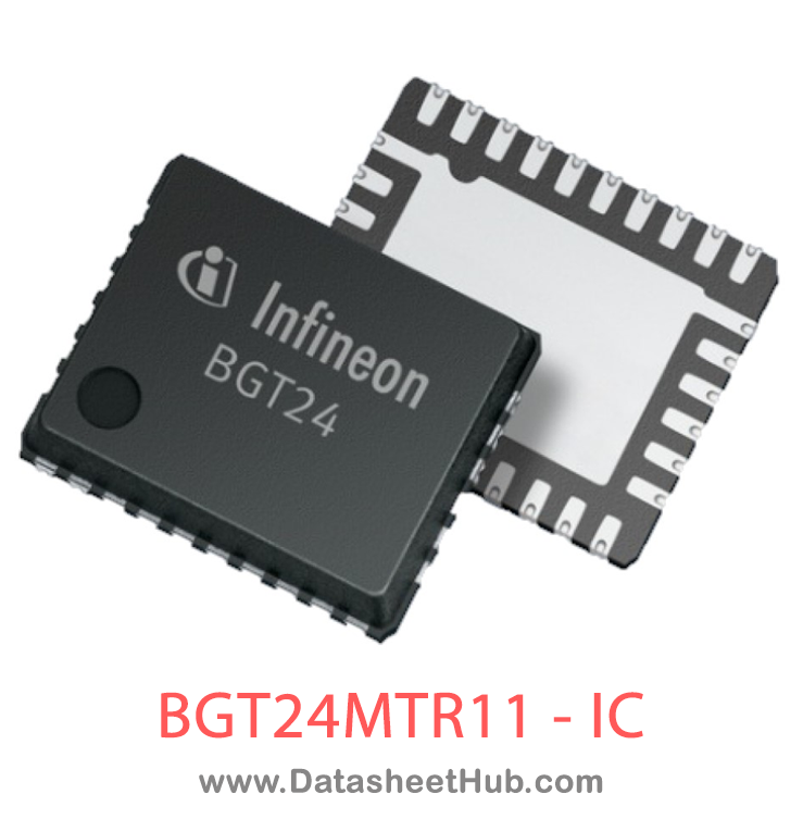
BGT24MTR11 overview
The BGT24MTR11 is a Silicon Germanium 24 GHz Transceiver MMIC made by Infineon Technologies AG, supplied in a VQFN32-9 Type package. The absolute maximum ratings table on this page lists the 20 limits from the manufacturer's datasheet that must not be exceeded. This page brings together the BGT24MTR11 pinout and maximum ratings, with the full datasheet PDF to preview below or download.
The BGT24MTR11 is a Silicon Germanium MMIC for signal generation and reception, operating from 24.0 up to 26.0 GHz. It is based on a 24 GHz fundamental voltage controlled oscillator. Switchable frequency prescalers are included with output frequencies of 1.5 GHz and 23 kHz. The main RF output delivers typ. 11dBm signal power to feed an antenna and an auxiliary LO output is available to provide LO signal to separate receiver components.
A LNA provides low noise figure and a RC polyphase filter (PPF) is used for LO quadrature phase generation of the homodyne quadrature downconversion mixer. Output power sensors as well as a temperature sensor are implemented for monitoring purposes. The device is controlled via SPI and is manufactured in a 0.18µm SiGe:C technology offering a cutoff frequency of 200 GHz. The MMIC is packaged in a 32 pin leadless RoHs compliant VQFN package.
Datasheet
BGT24MTR11 features
- 24 GHz transceiver MMIC
- Fully integrated low phase noise VCO
- Switchable prescaler with 1.5 GHz and 23 kHz output
- On chip power and temperature sensors
- Gilbert based homodyne quadrature receiver
- Single ended RF and LO terminals
- Low noise figure NFSSB: 12 dB
- High conversion gain: 26 dB
- High 1 dB input compression point: -12 dBm
- Single supply voltage 3.3 V
- Power consumption 500 mW in continuous operating mode
- 200 GHz bipolar SiGe:C technology b7hf200
- Fully ESD protected device
- VQFN-32-9 leadless plastic package incl. LTI feature
- Pb-free (RoHS compliant) package
BGT24MTR11 pinout
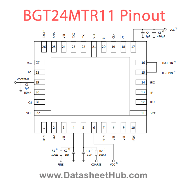
| Pin | Name | Description |
|---|---|---|
| 1 | Q1N | Complementary prescaler output 1.5GHz |
| 2 | Q2 | Prescaler output 23kHz |
| 3 | VEE | Ground |
| 4 | FINE | VCO fine tuning input |
| 5 | COARSE | VCO coarse tuning input |
| 6 | VCC | Supply voltage; Total current divided equal on both VCC pins |
| 7 | RFIN | RF input downconverter |
| 8 | VEE | Ground |
| 9 | VEE | Ground |
| 10 | IFQX | Complementary quadrature phase IF output downconverter |
| 11 | VEE | Ground |
| 12 | IFQ | Quadrature phase IF output downconverter |
| 13 | IFI | In phase IF output downconverter |
| 14 | IFIX | Complementary in phase IF output downconverter |
| 15 | TEST PIN | Test pin; DC coupled pin |
| 16 | TEST PIN | Test pin; DC coupled pin |
| 17 | VCC | Supply voltage; Total current divided equal on both VCC pins |
| 18 | CS | Chip select input SPI (inverted) |
| 19 | CLK | Clock input SPI interface |
| 20 | SI | Data input SPI interface |
| 21 | VEE | Ground |
| 22 | TX | Transmit output |
| 23 | TXX | Complementary transmit output |
| 24 | VEE | Ground |
Show all 32 pins
| Pin | Name | Description |
|---|---|---|
| 25 | ANA | Analog output |
| 26 | TXOFF | Pulsable Pin / Please connect to VEE in case TXOFF function is controlled via SPI |
| 27 | n.c. | Not connected |
| 28 | LO | LO output |
| 29 | VCCTEMP | Temperature sensor supply voltage |
| 30 | TEMP | Temperature sensor output |
| 31 | Q1 | Prescaler output 1.5GHz |
| 32 | VEE | Ground |
Absolute maximum ratings
| Parameter | Symbol | Value | Unit | Conditions |
|---|---|---|---|---|
| Supply voltage | VCC / VCCTEMP | -0.3 | – | 3.6 |
| DC voltage at RF Pins TX, TXX, LO, RFIN1, RFIN2 | VDCRF | 0 | – | 0 |
| DC voltage at Pins IFI, IFIX, IFQ, IFQX | VDCIF | 0 | – | Vcc |
| DC current into Pins IFI, IFIX, IFQ, IFQX | IIF | -8.5 | – | 3.5 |
| DC voltage at Pin ANA | VDCANA | -0.3 | – | 3.6 |
| DC current into Pin ANA (Sink) | IANA SINK | 125 | 350 | 500 |
| DC current into Pin ANA (Source) | IANA SOURCE | -7 | – | – |
| DC voltage at Pin TEMP | VDCTEMP | 0 | – | Vcc |
| DC current into Pin TEMP | ITEMP | -1 | – | 1.5 |
| DC voltage at Pins Q1, Q1N | VDCQ1x | Vcc-0.3 | – | Vcc |
| DC current into Pins Q1, Q1N | IQ1x | -8 | – | 12 |
| DC voltage at Pin Q2 | VDCQ2 | -0.3 | – | 3.6 |
| DC current into Pin Q2 enabled | IQ2EN | -3 | – | 3 |
| DC current into Pin Q2 disabled | IQ2DIS | -10 | – | 10 |
| DC voltage at SPI input Pins SI, CLK, CS | VDCSPIIN | -0.3 | – | 3.6 |
| DC voltage at Pins Fine, Coarse | VFine, VCoarse / 0 / – / 5 / V / – | |||
| DC current into Pins Fine, Coarse | IFine, ICoarse / -1 / – / 0.11 / mA / Positive currents if VTUNE > VCC | |||
| DC voltage at Pin TXOFF | VDCTXOFF / -0.3 / – / 3.6 / V / – | |||
| Total power dissipation | PDISS / – / – / 750 / mW / With BIST deactivated | |||
| Storage temperature range | TSTG / -40 / – / 150 / °C / – |
BGT24MTR11 applications
- Automotive Radar Systems
- Industrial Radar Sensors
- Short-Range Communication
- Microwave Imaging
Comments 0
Leave a comment