

LM3914 Datasheet – Dot/Bar Display Driver IC
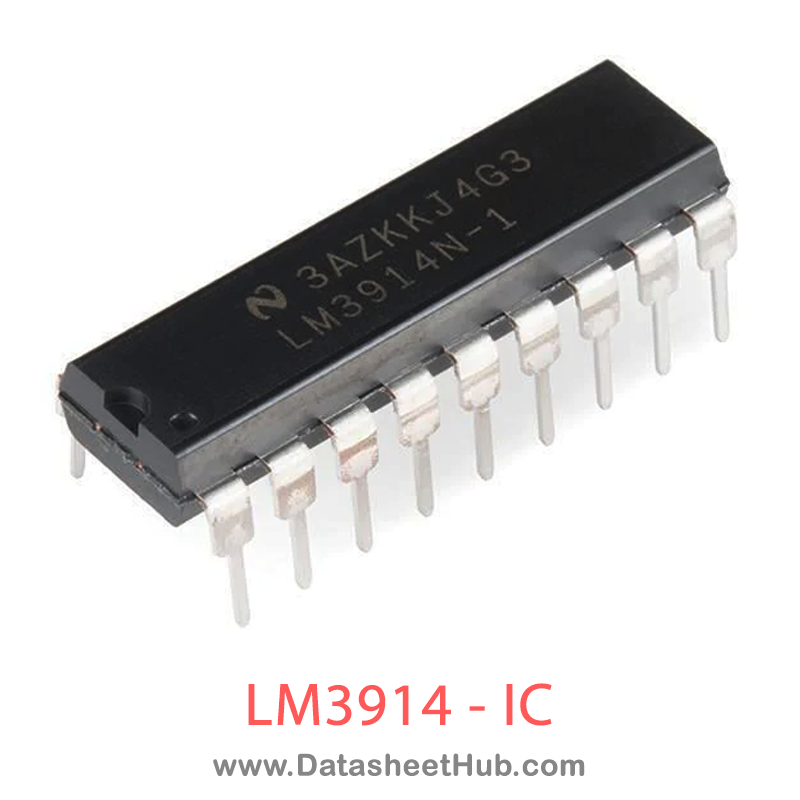
LM3914 overview
The LM3914 is a Display Driver made by Texas Instruments, supplied in a DIP-18 package. The absolute maximum ratings table on this page lists the 9 limits from the manufacturer's datasheet that must not be exceeded. This page brings together the LM3914 pinout and maximum ratings, with the full datasheet PDF to preview below or download.
The LM3914 is a monolithic integrated circuit that senses analog voltage levels and drives 10 LEDs, providing a linear analog display. A single pin changes the display from a moving dot to a bar graph. Current drive to the LEDs is regulated and programmable, eliminating the need for resistors. This feature is one that allows operation of the whole system from less than 3V.
The circuit contains its own adjustable reference and accurate 10-step voltage divider. The low-bias-current input buffer accepts signals down to ground, or V−, yet needs no protection against inputs of 35V above or below ground. The buffer drives 10 individual comparators referenced to the precision divider. Indication non-linearity can thus be held typically to 1⁄2%, even over a wide temperature range.
Versatility was designed into the LM3914 so that controller, visual alarm, and expanded scale functions are easily added on to the display system. The circuit can drive LEDs of many colors, or low-current incandescent lamps. Many LM3914s can be “chained” to form displays of 20 to over 100 segments. Both ends of the voltage divider are externally avail- able so that 2 drivers can be made into a zero-center meter.
The LM3914 is very easy to apply as an analog meter circuit. A 1.2V full-scale meter requires only 1 resistor and a single 3V to 15V supply in addition to the 10 display LEDs. If the 1 resistor is a pot, it becomes the LED brightness control. The simplified block diagram illustrates this extremely simple ex- ternal circuitry.
When in the dot mode, there is a small amount of overlap or “fade” (about 1 mV) between segments. This assures that at no time will all LEDs be “OFF”, and thus any ambiguous dis- play is avoided. Various novel displays are possible.
Much of the display flexibility derives from the fact that all outputs are individual, DC regulated currents. Various effects can be achieved by modulating these currents. The individual outputs can drive a transistor as well as a LED at the same time, so controller functions including “staging” control can be performed. The LM3914 can also act as a programmer, or sequencer.
The LM3914 is rated for operation from 0˚C to +70˚C. The LM3914N-1 is available in an 18-lead molded (N) package. The following typical application illustrates adjusting of the reference to a desired value, and proper grounding for accurate operation, and avoiding oscillations.
Datasheet
LM3914 features
- Drives LEDs, LCDs or vacuum fluorescents
- Bar or dot display mode externally selectable by user
- Expandable to displays of 100 steps
- Internal voltage reference from 1.2V to 12V
- Operates with single supply of less than 3V
- Inputs operate down to ground
- Output current programmable from 2 mA to 30 mA
- No multiplex switching or interaction between outputs
- Input withstands ±35V without damage or false outputs
- LED driver outputs are current regulated, open-collectors
- Outputs can interface with TTL or CMOS logic
- The internal 10-step divider is floating and can be referenced to a wide range of voltages
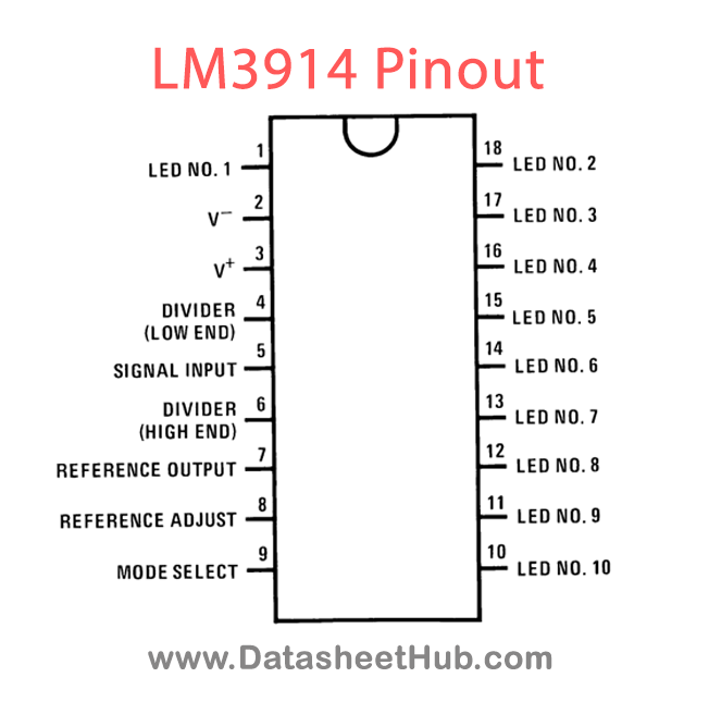
LM3914 pinout
Absolute maximum ratings
| Parameter | Value |
|---|---|
| Power Dissipation Molded DIP (N) | 1365 mW |
| Supply Voltage | 25V |
| Voltage on Output Drivers | 25V |
| Input Signal Overvoltage | ±35V |
| Divider Voltage | −100 mV to V+ |
| Reference Load Current | 10mA |
| Storage Temperature Range | −55˚C to +150˚C |
| Soldering Information Dual-In-Line Package Soldering (10 seconds) | 260˚C |
| Plastic Chip Carrier Package Vapor Phase (60 seconds) Infrared (15 seconds) | 215˚C220˚C |
LM3914 applications
- “Slow” — fade bar or dot display (doubles resolution)
- 20-step meter with single pot brightness control
- 10-step (or multiples) programmer
- Multi-step or “staging” controller
- Combined controller and process deviation meter
- Direction and rate indicator (to add to DVMs)
- Exclamation point display for power saving
- Graduations can be added to dot displays. Dimly light ev- ery other LED using a resistor to ground
- Electronic “meter-relay” — display could be circle or semi-circle
- Moving “hole” display — indicator LED is dark, rest of bar lit
- Drives vacuum-fluorescent and LCDs using added pas- sive parts
Comments 0
Leave a comment