

MP8670DN Datasheet – 6A, 30V, Step-Down Converter – MPS
6A, 30V, 420KHz Step-Down Converter with Synchronize able Gate Driver
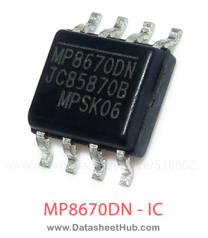
MP8670DN overview
The MP8670DN is a 6A, 30V, 420KHz Step-Down Converter with Synchronize able Gate Driver made by Monolithic Power Systems, supplied in an SOP-8 Type package. The absolute maximum ratings table on this page lists the 7 limits from the manufacturer's datasheet that must not be exceeded. This page brings together the MP8670DN pinout and maximum ratings, with the full datasheet PDF to preview below or download.
The MP86884 is a monolithic half-bridge with built-in internal power MOSFETs and gate drivers. It achieves 55A of continuous output current over a wide input supply range.
Integration of the driver and MOSFETS results in high efficiency due to optimal dead time control and parasitic inductance reduction.
The MP86884 is a Monolithic IC approach to drive up to 55A per phase. This very small 6mmx6mm TQFN device can operate from 100kHz to 1MHz.
This device works with tri-state output controllers. It also comes with a general- purpose current sense and temperature sense.
The MP86884 is ideal for server applications where efficiency and small size are a premium.
Datasheet
MP8670DN features
- Wide 4.5V to 14V Operating Input Range
- Simple Logic Interface
- 55A Output Current
- Accepts Tri-State PWM Signal
- Built-In Switch for bootstrap
- Current Sense
- Temperature Sense
- Current Limit Protection
- Used for Multi-Phase Operation
- Available in 6mm x 6mm TQFN Package
MP8670DN pinout
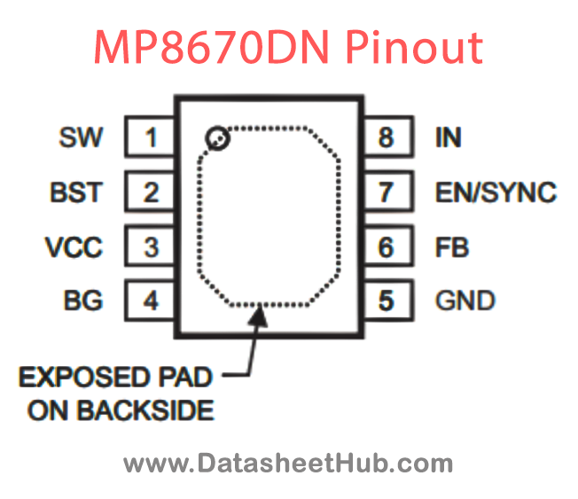
| Pin | Name | Description |
|---|---|---|
| 1-6 Exposed Pad | SW | Switch Output. |
| 7 | VDDDRV | Driver Voltage. Connect to 5V supply and decouple with 1µF to 4.7µF ceramic capacitor. |
| 8-21 Exposed Pad | PGND | Power Ground. |
| 22-23 Exposed Pad | IN | Supply Voltage. Place CIN close to the device to prevent large voltage spikes at the input. |
| 24 | EN | Enable. Pull low to place SW in a high impedance state. |
| 25 | VTEMP | Single pin temperature sense output. |
| 26 | T2 | Test pin. Connect to ground. |
| 27 | T1 | Test pin. Connect to ground. |
| 28 | CS | Current Sense Output. Requires an external resistor. |
| 29 | DT | Dead Time. It is recommended to float this pin to use default dead time setting. |
| 30 | VSS | Signal Ground. |
| 31 | VDD | Internal Circuitry Voltage. Connect to VDDDRV thru 2.2Ω resistor and decouple with 1µF capacitor to VSS. Connect VSS and PGND at this point. |
| 32 | PWM | Pulse Width Modulation. Leave PWM floating or drive to mid-state to put SW in high impedance state. |
| 33 | SYNC | Synchronous Low Switch. Leave open or pull high to enable. Pull low to enter diode emulation mode. |
| 34 | BST | Bootstrap. Requires a 0.22µF to 1µF capacitor to drive the power switch’s gate above the supply voltage. Connects between SW and BST pins to form a floating supply across the power switch driver. |
Absolute maximum ratings
| Parameter | Value |
|---|---|
| VSW (DC) | -1 V to 15V |
| VSW (25ns) | -3V to 23V |
| Instantaneous Current | 100A |
| Continuous Power Dissipation (TA =+25°C)(2) | 4.3W |
| Junction Temperature | 150°C |
| Lead Temperature | 260°C |
| Storage Temperature | -65°C to +150°C |
MP8670DN applications
- Server Core Voltage
- Graphic Card Core Regulators
- Power Modules
Comments 0
Leave a comment