
Digital Keypad Security Door Lock using Arduino overview
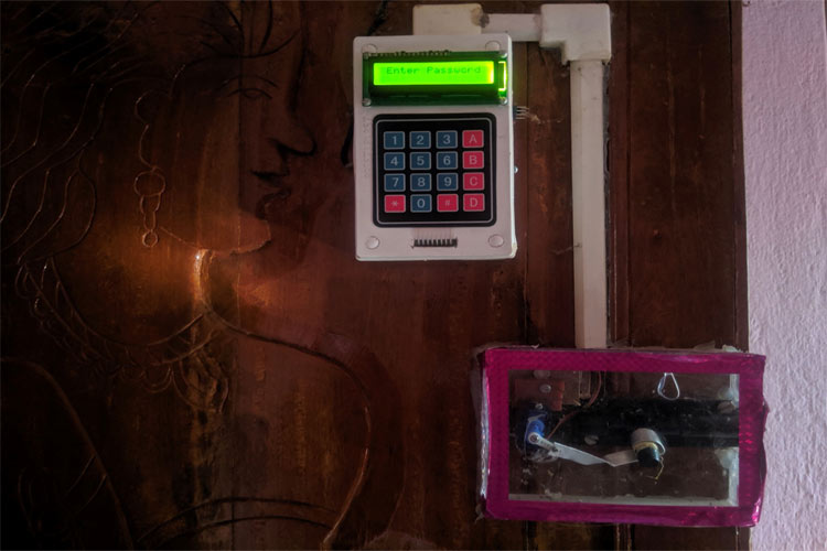
Often times, we need to secure a room at our home or office (perhaps a secret dexter’s laboratory) so that no one can access the room without our permission and ensure protection against theft or loss of our important accessories and assets. There are so many types of security systems present today but behind the scene, for authentication they all relay on fingerprint, retina scanner, iris scanner, face id, tongue scanner, RFID reader, password, pin, patterns, etc. Off all the solutions the low-cost one is to use a password or pin-based system. So, in this project, I have built an Arduino Keypad Door Lock which can be mounted to any of your existing doors to secure them with a digital password. Previously, we have also built other interesting door locks which are listed below
List of components
| Arduino Uno/Pro/Mini or Custom board using Atmega 328p Microcontroller | ||
| 16 x 2 LCD (Liquid Crystal Display) | ||
| 4 x 3 or 4 x 4 matrix keypad for Arduino | ||
| Servo motor | ||
| 3D printed door locker/customized door locker | ||
| Additional components for power supply of 1 Amp 5 Volt mobile charger | ||
| 4’’ / 6’’plastics boxes, jumper wires, nuts bolts, plastic casing, etc. |
The Complete circuit diagram for our Arduino based Digital Keypad Door Lock project is shown below.
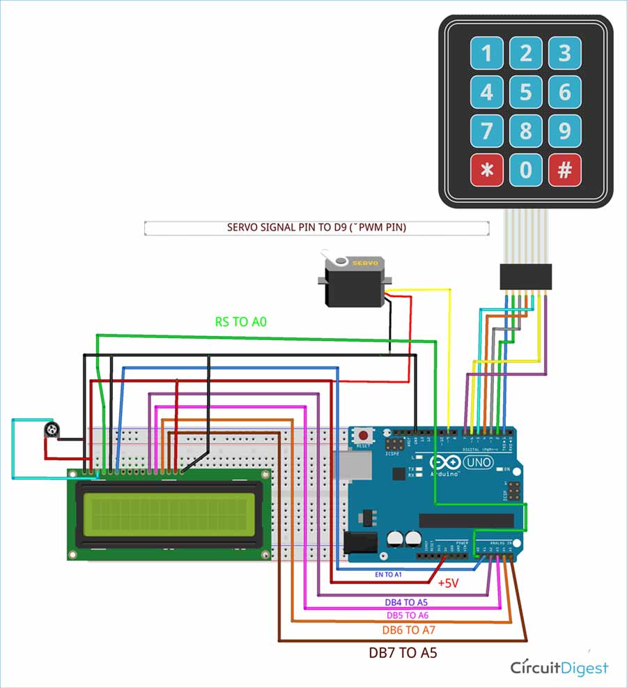
First of all, we start from the brain of this project which is the Arduino UNO board. The Arduino board is connected to an LCD and a servo motor. The servo motor is used to push (lock) or pull (unlock) the latch on the door. A 16 x 2 LCD is required to display the message by Arduino, 16 x 2 means it has 16 number of columns and 2 number of rows. If you are completely new to 16x2 LCD Display Modules, you can check this Arduino LCD Interfacing tutorial to learn more about it.
Here, I am using a 5v Towerpro SG90 servo motor for making our customized door locker. It is a basic level servo motor and works fine with Arduino without any driving circuit or external module. Also, the cost of this servo motor is very less so you can easily afford to buy it. You can also check this Arduino Servo Motor Control tutorial to learn more about the servo motor and how it works. Connect the servo motor with Arduino Digital pin D9 and with a 5volt power supply. This servo motor has a total of 3 input lines (GND, +5V & SIGNAL LINE).
In this project, I have used a 4 x 4 matrix keypad (but the 4 x 4 keypad part is not available in fritzing for making this graphical representation), but don’t worry as 4 x 3 Matrix keypad also works fine with my coding. We need a keypad for password input and manually lock our customized door locker. It consists of 16 keys (soft switch) 4 keys in Rows (R1, R2, R3, R4) and 4 keys in Columns (C1, C2, C3, C4) when a key pressed, it establishes a connection in between the corresponding rows and columns. The below table shows how to connect your Arduino with Keypad.
| Keypad | Arduino |
| Pin 1 (row 1) | Digital Pin1 |
| Pin 2 (row 2) | Digital Pin 2 |
| Pin 3 (row 3) | Digital pin 3 |
| Pin 4 (row 4) | Digital pin 4 |
| Pin 5 (columns 5) | Digital pin 5 |
| Pin 6 (columns 6) | Digital pin 6 |
| Pin 7 (columns 7) | Digital pin 7 |
The complete Arduino Door Lock Code can be found at the bottom of this page. You can directly upload the code, but it is recommended to read the below paragraphs to understand how the code works. Also, it is important to make sure you have added the following keypad library to your Arduino IDE to compile the code successfully. To do that just open the link below and download the ZIP file. Then on your Arduino IDE navigate to Sketch -> Include Library -> Add.ZIP Library and browse for the file that you just downloaded.
Comments 0
Leave a comment