
WROOM ESP32 Wifi Based Microcontroller Development Board
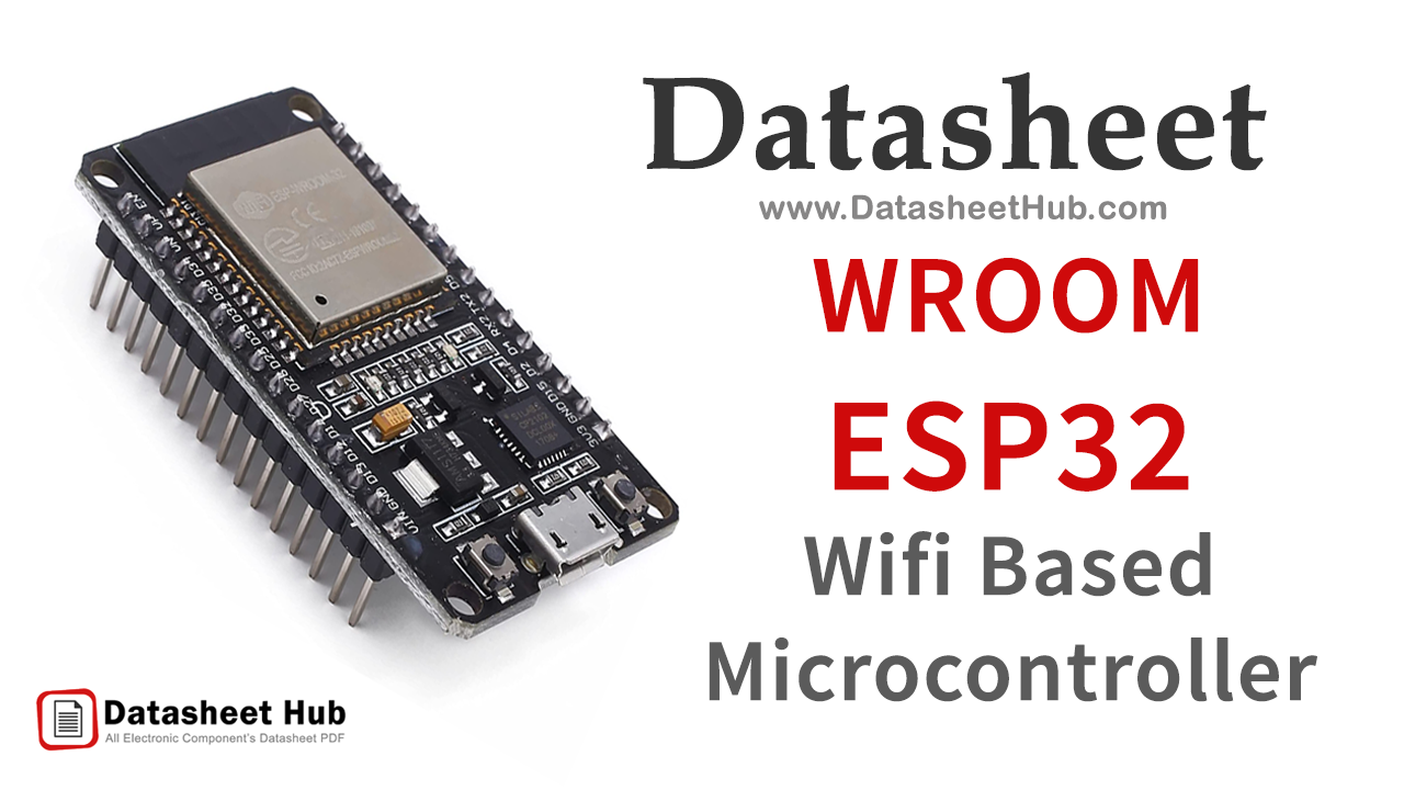
WROOM ESP32 Wifi Based Microcontroller Development Board overview
Espressif Systems, a Shanghai-based company introduced the latest version of its Wi-Fi and Bluetooth enabled System on Chip microcontroller ESP32 also known as ESP32 WROOM. The popularity of Iot has grown during the past years and hence the IoT enabled devices has become one of the most demanding devices for the technological peers and engineers, ESP chips are among those. ESP WROOM 32 has captured the attention due to its wide range uses and compelling performance compared to the previous ESP modules.
ESP WROOM 32 is a dual-core 32-bit all-powerful, universal Wi-Fi, BT (Bluetooth), BLE (Bluetooth LE) enabled MCU module that allows an extensive range of applications. It can be connected through the phone conveniently or can send the low-energy beacons to detect it using BT feature, while the Wi-Fi allows the uninterrupted internet connection through router. The dual-core MCU operates at 240 MHz and provides 600 DMIPS of processing capability; while one of its core controls the high speed connectivity, and the other is used for developing standalone applications.
The features and specifications of the ESP WROOM 32 module are described below.
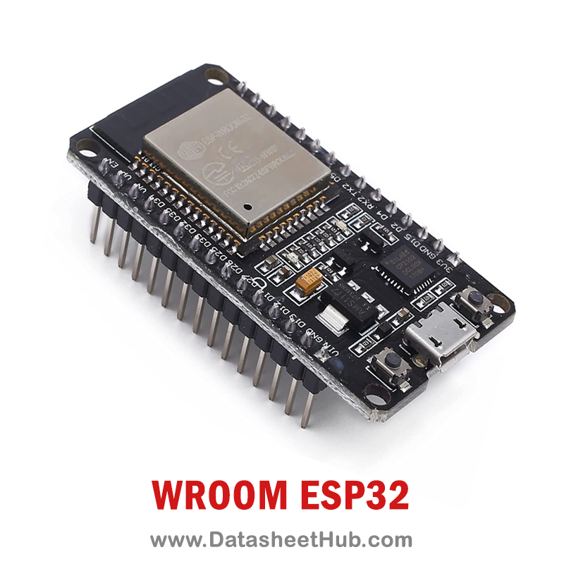
Key specifications
WROOM ESP32 Wifi Based Microcontroller Development Board features
- Hybrid Wi-FI & Bluetooth.
- High level of integration.
- Ultra-low-power management.
- 4 MB Flash.
- On-board PCB antenna.
- Integrated 520 KB SRAM
WROOM ESP32 Wifi Based Microcontroller Development Board pinout
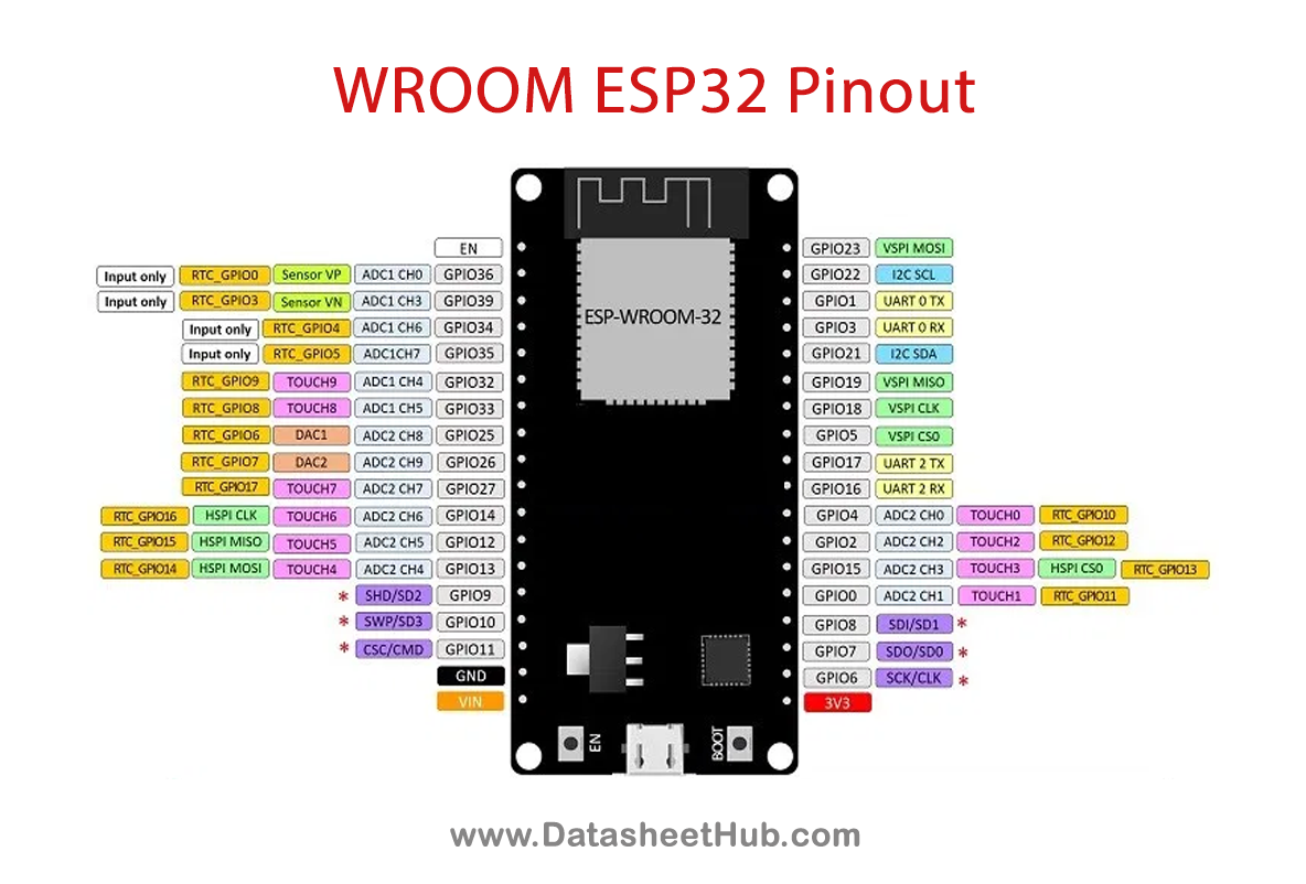
| Name | Description |
|---|---|
| Power | Micro-USB: ESP32 can be powered through USB port5V: Regulated 5V can be supplied to this pin which is we be again regulated to 3.3V by on-board regulator, to power the board.3.3V: Regulated 3.3V can be supplied to this pin to power the board.GND: Ground pins. |
| Enable | The pin and the button reset the microcontroller. |
| Analog Pins | Used to measure analog voltage in the range of 0-3.3V.12-bit 18 Channel ADC |
| DAC pins | Used for Digital to Analog Conversion |
| Input/Output Pins | Totally 39 GPIO pins, can be used as input or output pins. 0V (low) and 3.3V (high). But pins 34 to 39 can be used as input only |
| Capacitive Touch pins | These 10 pins can be used as touch pins normally used for capacitive pads |
| RTC GPIO pins | These 18 GPIO pins can be used to wake up the ESP32 from deep sleep mode. |
| Serial | Used to receive and transmit TTL serial data. |
| External Interrupts | Any GPIO can be used to trigger an interrupt. |
| PWM | 16 independent channel is available for PWM any GPIO can be made to work as PWM through the software |
| VSPI | Used for SPI-1 communication. |
| HSPI | Used for SPI-2 communication. |
| IIC | Used for I2C communication. |
| AREF | To provide a reference voltage for input voltage. |
WROOM ESP32 Wifi Based Microcontroller Development Board specifications
| Current – Receiving | 80 mA. |
|---|---|
| Voltage – Supply | 2.2 V ~ 3.6 V. |
| Current – Transmitting | 80 mA. |
| A number of pins supported | 30 |
| Data Rate | 54 Mbps. |
| Frequency | 2.4 GHz. |
| Mounting Type | Surface Mount. |
| Operating Temperature | -40°C ~ 85°C. |
| Power – Output | 16.5dBm. |
| Protocol | 802.11b/g/n/d/e/i. |
| RF Family/Standard | WiFi. |
| Sensitivity | -98dBm. |
| Serial Interfaces | I²C, I²S, SPI, UART. |
WROOM ESP32 Wifi Based Microcontroller Development Board applications
- Universal low-power IoT sensor hub.
- Home automation.
- Universal low-power IoT recorder.
- Mesh network.
- Video streaming of the camera.
- Industrial wireless control.
- OTT TV box / set-top box device.
- Baby monitor.
- Smart Socket.
- Sensor networks.
- Wi-Fi toys: Counters, toys, Anti-lost device.
- Wearable electronic products.
- Wi-Fi speech recognition device.
- Wi-Fi location-aware devices.
More about WROOM ESP32 Wifi Based Microcontroller Development Board
Pinout of ESP32 Microcontroller
| Pin Category | Pin Name | Details |
| Power | Micro-USB, 3.3V, 5V, GND | Micro-USB: ESP32 can be powered through USB port5V: Regulated 5V can be supplied to this pin which is we be again regulated to 3.3V by on-board regulator, to power the board.3.3V: Regulated 3.3V can be supplied to this pin to power the board.GND: Ground pins. |
| Analog Pins | ADC1_0 to ADC1_5 and ADC2_0 to ADC2_9 | Used to measure analog voltage in the range of 0-3.3V.12-bit 18 Channel ADC |
| DAC pins | DAC1 and DAC2 | Used for Digital to Analog Conversion |
| Input/Output Pins | GPIO0 to GPIO39 | Totally 39 GPIO pins, can be used as input or output pins. 0V (low) and 3.3V (high). But pins 34 to 39 can be used as input only |
| Capacitive Touch pins | T0 to T9 | These 10 pins can be used as touch pins normally used for capacitive pads |
| RTC GPIO pins | RTCIO0 to RTCIO17 | These 18 GPIO pins can be used to wake up the ESP32 from deep sleep mode. |
| Serial | Rx, Tx | Used to receive and transmit TTL serial data. |
| External Interrupts | All GPIO | Any GPIO can be used to trigger an interrupt. |
| PWM | All GPIO | 16 independent channel is available for PWM any GPIO can be made to work as PWM through the software |
| VSPI | GPIO23 (MOSI), GPIO19(MISO), GPIO18(CLK) and GPIO5 (CS) | Used for SPI-1 communication. |
| HSPI | GPIO13 (MOSI), GPIO12(MISO), GPIO14(CLK) and GPIO15 (CS) | Used for SPI-2 communication. |
| IIC | GPIO21(SDA), GPIO22(SCL) | Used for I2C communication. |
Datasheet ESP32 Microcontroller
Download WROOM ESP32 Microcontroller Datasheet from the link given below.
Comments 0
Leave a comment