
Arduino MKR Zero Developer Board
Arduino MKR Zero Developer Board overview
The Arduino MKR Zero brings the capability of a Zero board in a smaller format established by the MKR form factor. The Arduino MKR Zero board acts as a very useful tool for the implementation of 32-bit application development. The board is powered by Atmel’s SAMD21 MCU, which features a 32-bit ARM Cortex® M0+ core. The board contains everything needed to support the microcontroller; requiring the user to simply connect it to a computer with a micro-USB cable or power it with a LiPo battery. The battery voltage can also be monitored since a connection between the battery and the analog converter of the board exists.
The Arduino MKR Zero is a development board directed towards the needs of musicians and audio engineers The board is equipped with an onboard SD card holder and dedicated SPI interfaces (SPI1), allowing the user to be able to play music files without extra hardware.

Key specifications
Datasheet
Arduino MKR Zero Developer Board features
- Powered by Atmel’s SAMD21 MCU
- 32-bit ARM Cortex® M0+ core
- Atmel’s Embedded Debugger (EDBG)
- Equipped with full Debug interface
- micro SD card holder
- Dedicated SPI holders
- Ease-of-use for software debugging
- EDBG supports a virtual COM port that can be used for device and bootloader programming.
Arduino MKR Zero Developer Board pinout
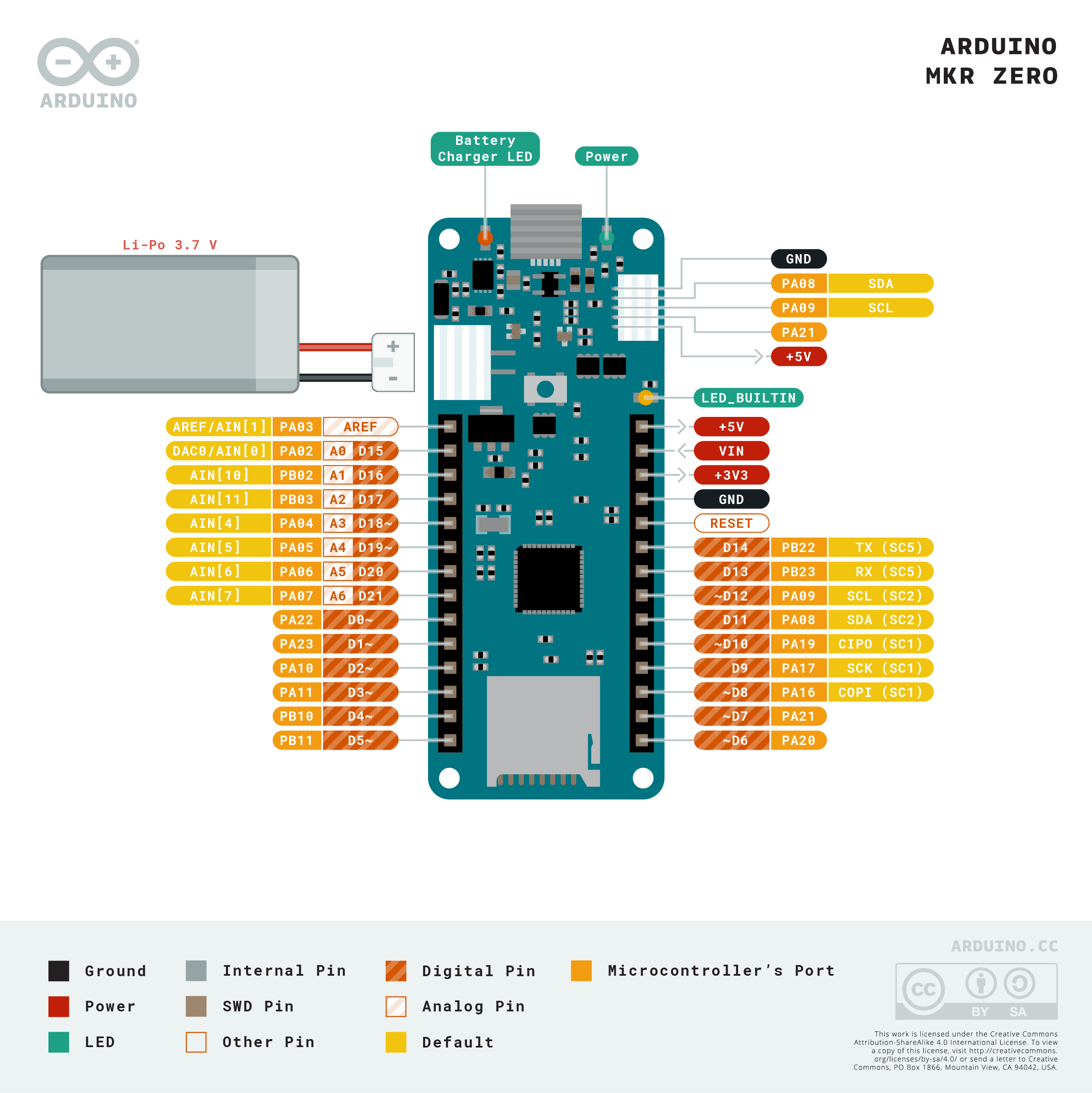
| Pin | Name | Description |
|---|---|---|
| 1 | AREF | Analog Reference Voltage |
| 2 | D15/A0 | Digital input 15 /GPIO/Analog In 0 |
| 3 | D/16A1 | Digital input 16 /GPIO/Analog In 1 |
| 4 | D17/A2 | Digital input 17 /GPIO/Analog In 2 |
| 5 | D18/A3 | Digital input 18 /GPIO/Analog In 3 |
| 6 | D19/A4 | Digital input 19 /GPIO/Analog In 4 |
| 7 | D20/A5 | Digital input 20 /GPIO/Analog In 5 |
| 8 | D21/A6 | Digital input 21 /GPIO/Analog In 6 |
| 9 | D0 | Digital input 0 |
| 10 | D1 | Digital input 1 |
| 11 | D2 | Digital input 2 |
| 12 | D3 | Digital input 3 |
| 13 | D4 | Digital input 4 |
| 14 | D5 | Digital input 5 |
| 15 | D6 | Digital input 6 |
| 16 | D7 | Digital input 7 |
| 17 | D8 | Digital input 8 |
| 18 | D9 | Digital input 9 |
| 19 | D10 | Digital input 10 |
| 20 | D11 | Digital input 11 |
| 21 | D12 | Digital input 12 |
| 22 | D13 | Digital input 13 |
| 23 | D14 | Digital input 14 |
| 24 | REST | Reset Pin |
Show all 28 pins
| Pin | Name | Description |
|---|---|---|
| 25 | GND | Ground Pin |
| 26 | +3V3 | Chip Supply Voltage 3.3V |
| 27 | Vin | Voltage Input |
| 28 | 5V | Chip Supply Voltage 5V |
Arduino MKR Zero Developer Board specifications
| MICROCONTROLLER | SAMD21 Cortex-M0+ 32bit low power ARM® MCU |
|---|---|
| BOARD POWER SUPPLY (USB/VIN) | 5V |
| SUPPORTED BATTERY(*) | Li-Po single cell, 3.7V, 700mAh minimum |
| DC CURRENT FOR 3.3V PIN | 600mA |
| DC CURRENT FOR 5V PIN | 600mA |
| CIRCUIT OPERATING VOLTAGE | 3.3V |
| DIGITAL I/O PINS | 22 |
| PWM PINS | 12 (0, 1, 2, 3, 4, 5, 6, 7, 8, 10, A3 - or 18 -, A4 -or 19) |
| UART | 1 |
| SPI | 1 |
| I2C | 1 |
| ANALOG INPUT PINS | 7 (ADC 8/10/12 bit) |
| ANALOG OUTPUT PINS | 1 (DAC 10 bit) |
| EXTERNAL INTERRUPTS | 10 (0, 1, 4, 5, 6, 7, 8, A1 -or 16-, A2 - or 17) |
| DC CURRENT PER I/O PIN | 7 mA |
| FLASH MEMORY | 256 KB |
| FLASH MEMORY FOR BOOTLOADER | 8 KB |
| SRAM | 32 KB |
| CLOCK SPEED | 32.768 kHz (RTC), 48 MHz |
| LED_BUILTIN | 32 |
Arduino MKR Zero Developer Board applications
- Traffic Light Count Down Timer.
- Parking Lot Counter.
- Embedded systems.
- Home Automation.
- Industrial Automation
More about Arduino MKR Zero Developer Board
Specifications
| EEPROM | no |
| FULL-SPEED USB DEVICE AND EMBEDDED HOST |
Datasheet
See Also: CD4059 Program Divide-by-N Counter | ADXL335 Accelerometer Sensor Module | SIM900A Dual Band GSM/GPRS Module
Comments 0
Leave a comment